Statistics: Posted by Augustica.com — 21 Dec 2016, 10:46
]]>

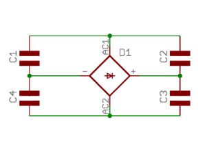
The circuit represents a pair of half wave rectifiers of opposite polarity, with output taken between the two. One capacitor is charged up to the peak AC voltage on the positive half cycle, and the other is charged up to the peak AC voltage on the negative half cycle. Sice the load is connected between these two capacitors, it receives the difference that equals of 2 Vpeak. Since C1 and C2 are both part of the total reservoir capacitance and each is charged on alternative half cycles, the total reservoir receives a charging pulse twice every mains cycle, so it is a full wave circuit. The two capacitors on the figure above have to have twice the capacitance rating of a capacitor used in a conventional full wave rectifier bridge circuit that uses four diodes connected in a bridge. The two capacitors on the figure above also have to handle twice the peak ripple current of a capacitor used in a conventional full wave bridge rectifier. However, the two capacitors only need to have half the voltage rating, since the total output voltage is shared equally between them. For a given load current the transformers need the same VA rating or, in other words, the transformer used for the voltage doubler must be rated for a half the AC voltage but twice the current as the equivalent conventional bridge rectifier circuit.
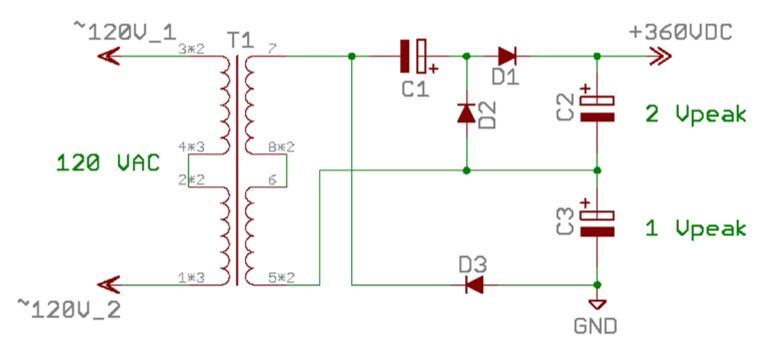
By taking the half wave voltage doubler and adding another half wave rectifier, we obtain a full wave voltage tripler depicted on the figure below. If we take the outputs between the two rectifiers then we obtain 3 Vpeak. Since C2 and C3 are each part of the total reservoir capacitance, and each is charged up on alternate half cycles, this now qualifies as a full wave rectifier circuit.
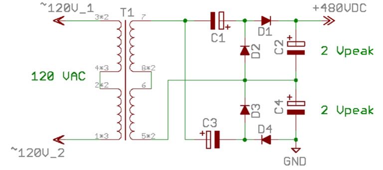
By connecting two half wave voltage doublers in parallel as shown on the figure below, we obtain a full wave voltage quadrupler.
When using a centre tapped transformer, it is possible to obtain several different voltage buses. The example of such topology is shown below.

Statistics: Posted by Augustica.com — 23 Nov 2013, 15:29
]]>
For example, the circuit in Fig A below is an ideal half wave rectifier producing about +100VDC from 70VAC transformer (remember, VDC = Vrmc x square root of 2). Thus, we know that there must be almost 100VDC across the capacitor. If we make the negative end of capacitor zero volts (ground) then other end must be +100VDC.

Alternatively, we could ground the positive end of the capacitor. There must still be 100V across the capacitor, so its negative end must now be -100VDC, as is shown on Fig B. Both circuits Fig A and Fig B work identically of course, all we have done it moved our frame of reference. We could also alter the direction of current flow by reversing the diode and capacitor, in which case we could devise the circuits as is shown on Fig C and Fig D.
Although A and C considered to be "normal" arrangements (perhaps because they are little more intuitive when drawn as a schematic) there is no reason why B and D could not be used to achieve the same results. this ability to shift our frame of reference and look at how a circuit works rather than what it looks like when compared with someone else's circuit is essential.
Depending on where we place the ground reference, rectifiers can be made to produce positive or negative DC voltages.

Statistics: Posted by Augustica.com — 29 Oct 2013, 10:33
]]>
Shielding against electric fields is relatively easy. Any bit metal will do, as long as it is connected to ground. The chassis provides the ultimate shield against external electrostatic noise, but shielding may still be required internally, either to protect sensitive wiring against noise coming from other areas, or to enclose noisy conditions and prevent their electric fields from permeating the air. The wires leading from the input jack to the first tube often need to be shielded to prevent them picking up larger AC voltages present at the far end of the amplifier, which would cause parasitic feedback.
Shielded cable can be bought specifically, but the DIY alternative is to scrounge it from cheap audio interconnects.
Noisy wiring should run close to the chassis wall or, better still be pushed into the corners to maximize the capacitance to earth. The earthed chassis will then have a similar effect to a Faraday cage and will tend to draw the electric field towards itself, this often eliminates any need to completely shield the wiring, especially filament wiring.
Shielding cans may be used for small tubes, and if the tube socket has a central spigot, then this can be grounded to to some convenient point, as it will offer some shielding between opposing pins. Some tubes like 6922 include an internal shield or screening cage that can also be grounded. Another technique used in some hi-fi circuits - which offers electric screening while leaving the valve on display - is to use a pentode as a triode. But instead of connecting the screen and anode together as would normally be the case, the anode is instead grounded while the screen alone is used as the anode. The real anode thus serves as a shield.
Large power supply smoothing capacitors can sometimes be placed to provide some screening between different parts of a circuit since the metal can is normally connected to the negative terminal, which is often grounded. Likewise, other grounded metal objects like smoothing chokes or reinforcing brackets can be used to advantage. in extreme cases the chassis may be partitioned into sections with bulkheads to create isolated chambers that are shielded from one another.
Take a note that shielding only attacks the symptoms of the problem. The more direct route is to reduce the source of the electric filed by minimizing AC voltages. In this sense, amplifiers operating from lower supply voltages have an advantage. In particular, it is much easier to avoid parasitic oscillation in high-gain designs by keeping supply voltages to a minimum - less than 300 Volt. After all, headroom is not a top priority in a high-gain design, sot there is no need to have large signal amplitudes in the preamplifier or headphone amplifier.
2. Magnetic Shielding
Shielding against magnetic fields is much more difficult than shielding electric fields for two reasons. Firstly, at low frequencies the metal used for shielding must have high magnetic permeability, which limits us to expensive materials like mu-metal (which si at least one hundred times better at magnetic shielding than steel). At high frequencies ordinary metals can be used for magnetic shielding because they allow eddy currents to be set up, which generate opposing magnetic fields to the ones creating them, but this is not much use for audio. Secondly, the shielding must form a completely unbroken band or box since the idea is to encourage the interfering flux to flow in the shield rather than in the thing being screened. Any breaks or seams will prevent magnetic flux from flowing in a complete loop in the shield, so the physical construction of the shield is critical. Signal transformers and inductors are extremely sensitive to picking up magnetic hum and often need multilayer shielding, so they are avoided wherever possible.
Explicit magnetic shielding is therefore rarely found in audio amplifiers. A mild steel chassis may have a slight magnetic advantage over stainless steel or aluminum, but it is hardly noteworthy. Instead, the most practical techniques for minimizing the effects of magnetic fields are to adopt a tight audio layout so that the area of any loops is minimized, and to keep transformers and high-current carrying wires well away from sensitive circuitry.
Statistics: Posted by Augustica.com — 24 Sep 2013, 19:14
]]>
It is difficult to shield against magnetic fields, so audio circuitry should always be placed as far away from any transformers as possible, especially the power transformer. The output transformer is not so much of a problem because it should have little or no hum current flowing in it. It does handle high primary voltages that generate strong electric fields, but it is much easier to shield against these. Nevertheless, it is usual to mount power and output transformers at the opposite end of the chassis from the input tubes.
The magnetic field around the power transformer will couple with output transformer to produce hum in the speaker, and the closer their proximity to each other the worse it will be. This works against us since ideally we want to mount them both at one end of the chassis away from the input tubes, but their interaction could be minimized by orienting them carefully. In theory, the axis of one transformer core should be kept orthogonal to the other to minimize coupling but, in practice, an apparently random orientation may provide the best performance. The perfect arrangement can be found at an early stage of construction by connecting a speaker or headphones to the secondary of the output transformer, and then connecting the mains supply to the power transformer. The output transformer can then be moved around the chassis while listening to the changes in hum. Obviously, great care must be taken when doing this, since the power transformer is live. It should then be possible to find some position where the hum reaches a minimum or becomes inaudible. If smoothing choke is used, it may be placed between the power and output transformers to provide a measure of shielding between the two. Its orientation is less important, but it it should be orthogonal to the output transformer where possible.
Transformers are usually mounted to the chassis with non-ferrous bolts and an insulating gasket or fibre washes to prevent the core flux from also flowing in the chassis, which might otherwise lead to hum getting into the ground circuit. However, this is unlikely to be a problem in a headphone amplifier, provided a sensible ground scheme has been employed.
Statistics: Posted by Augustica.com — 24 Sep 2013, 18:24
]]>
Ground Safety Bonding
The three wires leaving a domestic supply are line, neutral, and ground. Neutral and ground are connected together at the substation or possibly at the electricity supply company's cable head within the house. this means that if line contains ground, a fault current flows, determined by the ground loop resistance, which is the entire resistance around the loop, including the resistance of the line wire.
The purpose of the ground safety bond is to provide a sufficiently low resistance path to earth that if the line wire of the mains should come into contact with the exposed metalwork (which then would be a shock hazard), the resulting line to earth fault current is sufficiently great to rupture the fuse quickly. The time taken for the fuse to rupture is proportional to the ground loop resistance, so there is no such thing as an ground loop resistance that is too low.
Although exposed tubes may appear to conform with safety standards because the electrodes are insulated by a vacuum and the glass envelope, it the envelope is broken, the secondary layer of insulation also disappears. To ensure conformity, tubes on the top of the chassis should be enclosed by a perforated metal cover.
If you build an amplifier on a chassis with exposed metal, then the construction must be such that all hazardous voltages must be insulated from, and totally enclosed by, ground-bonded metalwork. the ideal place to achieve this bonding is close to the entry of the power cable. The bond should be made using a solder tag bolted to the chassis with a shakeproof (star) washer between the washer and the chassis because this bites in to the metal of the chassis and the tag to provide a gas-tight joint. If the chassis is anodized aluminum, the surface anodizing must be thoroughly scraped away underneath the tag to ensure a good bond.
The nut and bolt should be prevented from loosening using further shakeproof washers and/or locknuts. the ground bond bolt should never pass through plastic, such as the mains input socket, because plastic quickly creeps and causes the bond to loosen.
The ideal ground bond would weld the incoming ground wire from the mains cable directly to the chassis, but this is not very practical. A perfectly reasonable alternative takes the incoming ground wire directly to a solder tag, where it should form a mechanical soldering joint. The tag is then screwed to the chassis with a shakeproof washer either side of the chassis, and another shakeproof washer above the ground tag, followed by a flat washer (to prevent the tag rotation when the bolt is tightened), then secured with a locknut. the nut and screw should be firmly tightened with a large screwdriver and a spanner after soldering otherwise the secure bond to the chassis prevents the iron from heating the tag.
A thick cable should be used to bring mains ground to the bond point in order to reduce ground resistance. Although it is permissible for 3 A rated equipment to have 0.5 Ohm of resistance from the pin to the mains plug to the chassis (not measured directly at the bond point), reducing this resistance to o.1 Ohm, or less, by using 2.5 mm mains cable, reduces the likelihood of hum and further improves safety.
0 Volt System Grounding
it is the 0 V signal ground connection to chassis that causes the hum due to hum loops between multiple grounds, not the safety bond. Hum loops are circuits within ground paths that can have hum currents induced into them by mains transformers. Because there is resistance in the circuit, an unwanted voltage is developed, and this causes the audible hum. To remove the hum, the loop must be broken, and this is often done by removing the ground wire from within the mains plug of one of the affected pieces of equipment, but this is extremely dangerous. The loop should be broken by removing the 0 V signal ground bond to chassis from one of the pieces of equipment. Fortunately, most modern equipment is double insulated, so hum loops do not often occur.
Statistics: Posted by Augustica.com — 13 Aug 2013, 14:51
]]>
To save time on assembly and any subsequent maintenance, any fixing screw should be just long enough to use all of the thread in the nut and no longer, and this is particularly important when securing tube bases. Screws that are too extended on tube bases make heater wiring particularly difficult. Unfortunately, if you decouple your heaters to the chassis at the tube base with 10 nF capacitors, the necessary solder tags and star washers inevitably require a longer screw.
Electromagnetic Fields and Filament Wiring
The electromagnetic field is due to the current flowing in the power wires, which induces in any nearby signal wiring. This means that not only are tubes with 12.6V filaments cheaper, but they are better in terms of noise too. Halved filament current means 6dB less heater induced hum.
Filament wiring is usually taken from a winding on the mains transformer to the nearest tube, and looped through, from one tube to the next, until each tube has filament power. The input tube is the most sensitive stage, and this should be the last in the filament chain, in order that the wiring leading to this tube carries the least current.
To minimize the external electromagnetic field, the filament wire should be tightly twisted. This means that although any given twist induces a current of one polarity, the twists either side of it induce currents of opposite polarity, and so the fields tend to cancel. This twist should be maintained as close up to the pins of the tube as possible, and when one phase of the filament wire has to go to the opposite side of the base and return, as is the case when wiring past 12AX7 to the next tube, the wiring should go across the base and be twisted as it passes across. The worst way to wire filaments would take the incoming pair connecting to the two heaters pins from one side, then loop around the opposite side to form a circle of filament wiring around the tube base.
Filament wiring leading to tubes using B9A sockets such as EL84 is best twisted from 0.6 mm (conductor diameter) insulated solid core wire, which is rated at 1.5 A. Octal tubes generally require more filament current, so the larger tags on their sockets can accommodate thicker wire, which could not have been connected to the pins of B9A socket. When wiring to tubes other than rectifiers, it is useful to use a different colour for each phase such as black and blue. When wiring to a push-pull output stage, if the same colour goes to the same pin on each tube, then the hum induced within each tube will be the same phase, and will be cancelled in the output transformer. This assumes that both tubes were made by the same manufacturer under the same specifications.
Tube rectifiers such as GZ34 and GZ37 not only have a dedicated 5 V filament supply, but they also have the incoming high voltage AC, so the two should be clearly distinguished. We use a red twisted pair for B+, and a blue twisted pair for the filament.
Twisting wire is not difficult. Cut equal lengths of wire to be twisted, pair the wires together at one end and clamp them in a vise. Gently tension both wires equally at the far end, and grip them in the chuck of the drill. Hold the wires reasonably taut by pulling on the drill and start twisting. When the wire begins to accelerate you towards the vise it will have about ten twists per inch. Switch the drill off, and while maintaining tension by holding the wire with your fingers, undo the chuck. The wire will now try to untwist, and if allowed to do so suddenly, it will tie itself in knots. Gently release the tension in the wire and release from the vise. You now have perfectly twisted wire.
You will find that it is easier to achieve a perfect twist on longer lengths of wire than short ones, because it is easier to equalize the tension between the wires. Equal tension is important because if one wire is slack compared to the other, it tends to wrap itself around the tighter wire (which remains strait). For this reason, it is worth twisting 4 or 6 meters of wire at a time, but these longer lengths are more easily twisted with a power drill, whereas shorter lengths can be twisted with a hand drill.
Electromagnetic fields decay with the square of distance, so filament wiring runs should be as far away as possible from signal circuitry, and only come up to the tube at the last possible moment and in the most direct manner possible. Tube sockets should be oriented so that the pins receiving filament wiring are as close to the chassis wall as possible, and filament wire should never loop round a tube except for rectifier tubes, where hum is not an issue.
Electrostatic Fields and Filament Wiring
The electrostatic field is due to the voltage on the wiring. Filament wiring should be pushed firmly into the corners of the conductive chassis, since the electrostatic mirror at the corner tends to null some of the electrostatic field. Filament wiring must not run exposed from one tube to the next, but should return to the corner of the chassis to re-emerge at the next tube. These strictures mean that good filament wiring requires considerable time/cost, so modern commercial amplifiers sometimes skimp on the quality of their filament wiring.
AC filament wiring should be connected to the transformer in a balanced fashion. Unfortunately, filament wiring must have a DC path to B+ 0 volt in order to define the filament to cathode voltage, and this can be achieved in various ways. The worst way to define the DC path is simply to connect one side of a transformer winding to 0 Volt. This ensures that one phase of the wire induces no hum, while the other phase induces maximum hum.

The ideal way of defining the DC path is to use a transformer with a centre tap on the heater winding, but if this is not available, fixed or variable resistors can be used to derive a midpoint. Accurately matched resistors used to be rare, so a variable resistor known as humdinger control used to be fitted, and adjusted for minimum hum. Once a filament midpoint has been derived, and connected to B+ 0 Volt, each wire has equal voltage with opposite phase hum, adn electrostatic fields tend to cancel.
This hum cancellation technique is not perfect, and for ultimate reduction of filament induced hum, we should screen the filament wiring with braid or thin walled aluminum tubing (available from modeling shops), and/or use DC filament supplies. Even when using DC filament supplies, it is worth treating the filament wiring as if it were carrying AC, as this will ensure that the finished project has no filament induced hum. the output of a DC filament regulator has virtually no AC present, so the filament 0 Volt can be connected directly to the B+ 0 Volt.
Filament wiring is the first piece of wiring to go to a project, thereafter, it is obscured by signal wiring. Once all the other wiring is in place, it is impossible to replace the heater wiring, so it must be installed correctly. Because it is so difficult to make changes to filament wiring, it is a good idea to immediately do the mains wiring and test it all by plugging all the valves in and making sure that they glow.
Mains Wiring
Mains wiring should be as short and direct as possible because the wire's insulation is often quite thick, so it cannot be twisted well. Mains wiring inevitably generates considerable electrostatic interference fields, so put the mains switch near the back panel, and if necessary, add a mechanical linkage to bring its control to the front.
Modern semiconductor equipment sleeves all exposed mains wiring with rubber PVC sleeving such that it is moderately safe to rummage inside a piece of powered equipment. Valve amplifiers operate on such high voltages that it is never safe to rummage inside of powered equipment, and even unpowered equipment should be approached with caution. Safety is therefore not greatly improved by sleeving mains wiring, but it is still good practice to sleeve mains wiring with heatshrink sleeving or purpose-made rubber boots to fit over mains sockets and fuse holders. The mains connectors used on classic tube amplifiers are, without exception, outrageously dangerous.
Mains Switching
To switch a piece of equipment off, all we need to do is to break the circuit from the source power. A mains switch could therefore equally well be inserted in the live or neutral wire, and still perform the job, and this is known as single pole switching. However, a switch in the neutral leaves all internal mains wiring live and continues a shock hazard within the equipment. Single pole switching should therefore always switch off the live circuit to minimize shock hazard.
Double pole switching switches both the live and the neutral, and ensures safety even if the live and neutral wires are reversed. Where there is no possibility of live/neutral reversal, single pole switching is safer, and more reliable, because failure of the switch ensures a break in the live connection to circuitry. A double-pole switch has twise as many contacts to fail, and if the neutral contact fails, the equipment could appear to be safe, even though the mains wiring is connected to live mains, and still continues a shock hazard.
Statistics: Posted by Augustica.com — 12 Aug 2013, 21:27
]]>

One end of the voltage reference is connected to the OUT terminal and the other is an input to the error amplifier. The third terminal is the ADJ terminal. The 317 therefore strives to maintain a voltage equal to the reference voltage (1.25V) between the OUT and ADJ terminals. In datasheet for 317, you will find that R2 is equal to 240 Ohm. The reason for this is that the 317 must pass 5 mA before it can regulate reliably. If the potential divider passes 5 mA, then 317 is able to regulate even if there is no external load. Datasheets usually show 317 with the ADJ pin bypassed by a 10 uF electrolytic capacitor which improves ripple rejection from 60 dB to 80 dB at 100 Hz.
Single-ended amplifiers, whether pre-amplifiers or power amplifiers, supplied with voltage from a power supply with a regulator add a specific musical characteristics to the sound of amplifier. This is because the amplifier draws a current proportional to the amplitude of audio signal, and the regulator strives to maintain a constant voltage in the face of this changing current. At high frequencies, the output shunt capacitor is a short circuit and maintains a low output impedance, but at low frequencies, it is the regulator that must do the work, and cope with the audio current waveform. the quality of the regulator is therefore inevitably audible. Nevertheless, regulator defects are still an order of magnitude below passive power supply defects.
Statistics: Posted by Augustica.com — 08 Aug 2013, 20:09
]]>
As the AC waveform rises through 0V, one or more diodes in a rectifying bridge of a power supply will switch on. These diodes will stay switched on until the waveform falls through 0V, at which point the other diode or diodes will switch on. All diodes need a minimum forward bias before they will switch on. Silicon diodes typically require 0.7V. This implies that there is a dead zone positioned symmetrically about 0V when no diodes conduct. The transformer, being inductive, has been switched off, and tries to maintain the current flow, but in doing so, it generates a voltage. Fortunately, there are many stray capacitances within the transformer to prevent this voltage from rising very far, but if we are unlucky, the shock applied to the system may excite a resonance resulting in a damped chain of oscillations. Luckily, this problem could be cured by bypassing each individual diode with a 0.01 uF film capacitor having a voltage rating equal to the diode Vrrm rating.
Whether we use a bridge rectifier or a centre-tapped rectifier, we still apply the same waveform to the succeeding circuit. The waveform, although it is of only one polarity, is not a smooth DC. The function of the smoothening element is to reduce the ripple, either to a satisfactory level, or to a level such that a regulator can cope with it. The simplest way to smoothen the output of the rectifier is to connect a reservoir capacitor across it. and feed the load from this reservoir. Assuming no load current, the capacitor charges to the full peak value of the AC leaving secondary winding of the transformer which is determined by the formula below:

The output of the rectifier tops up the charge in the capacitor every cycle, so that at the peak of the waveform, the capacitor is fully charged. The voltage from the transformer then falls down sharply, and switch off the rectifier diodes. Load current is now supplied only from the capacitor C5, which discharges exponentially into the resistive load until the transformer output voltage rises sufficiently to recharge the capacitor, and restart the cycle.
Although the reservoir capacitor theoretically discharges exponentially, the discharge curve may be taken to be a straight line. And if the load is a series regulator, the discharge curve is certainly a strait line. Given this approximation, it is easy to calculate what the output ripple voltage will be. Let's assume that the output current of our power supply is 250 mA, then we are able to calculate Vripple by the following formula:
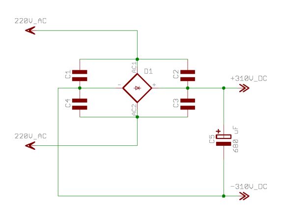
Accordingly, capacitor C5 has to have voltage rating of at least 310VDC.
The reservoir Capacitor C5 charges to the voltage peaks leaving the rectifier, so the ripple voltage is subtracted from the voltage leaving the rectifier and reduces the output voltage. The output voltage can be described to be made up of two components - VDC that is pure DC, and Vripple that is the superimposed AC ripple voltage. The significance of this fact is that subsequent filtering is required to filter AC component out to leave only the DC component.
Statistics: Posted by Augustica.com — 07 Aug 2013, 18:44
]]>