
I am very excited to get building my Frigate kit.
Having researched many headphone amps I conclude that you have created something very special.
I can not wait to hear the proof.
Would you show me some pictures of how the transformers get hooked up to the amp and the AC.
I am not clear which wires go where.
Can you send me clear instructions on how to measure the B-plus DC voltage
Do I use a multi meter to measure ?
Where do the probes make contact to take the measurement?
Also what setting do I use?
Frigate® build
9 posts
• Page 1 of 1
Re: Frigate® build
![]() by Augustica.com » 24 Dec 2013, 15:43
by Augustica.com » 24 Dec 2013, 15:43
I know that you are located in Toronto. Accordingly, I will provide photos and instructions which are only relevant for North American connection of the transformers as in the North America we have AC voltage of 120 Volt. Anyone who has a different AC voltage (for example 220 Volt) should not use these instructions. AC voltage of 220 Volt will require a different connection of the primarily leads of the transformers.
Below is the photo of the B+ transformer 182E110. Grey and Blue leads of the secondary coil are twisted together and isolated by electric tape. Yellow and Red leads of the secondary coil will be connected to the power supply Trident.
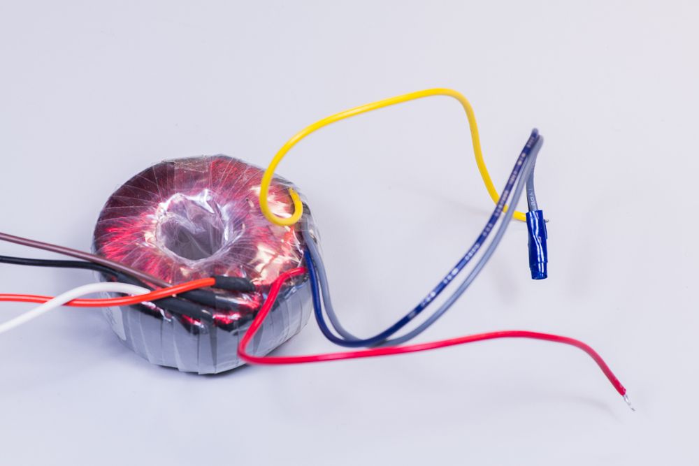
Below is the photo of the primary coil leads of 182E110 that are connected to power outlet. Brown and Black leads of the primary coil are twisted together and form one lead that connects to the power outlet. Red and White leads of the primary coil are twisted together and form another lead that connects to the power outlet.

This is another photo of the leads of the secondary coil of the 182E110 that are going to be connected to the power supply Trident.

Below is the photo of the filament transformer 182L12. Red and Blue leads of the secondary coil will supply filament voltage to the first filament bus of the power supply Trident. Yellow and Grey leads of the secondary coil will supply filament voltage to the second filament bus of the power supply Trident.

Below is the photo of the primary coil leads of 182L12 that are connected to power outlet. Brown and Black leads of the primary coil are twisted together and form one lead that connects to the power outlet. Red and White leads of the primary coil are twisted together and form another lead that connects to the power outlet.

Below is another photo of the leads of the secondary coil of the 182L12. Red and Blue leads of the secondary coil will supply filament voltage to the first filament bus of the power supply Trident. Yellow and Grey leads of the secondary coil will will supply filament voltage to the second filament bus of the power supply Trident.

Finally, below is the photo of 182E110 and 182L12 connected to the power supply Trident.

B+ DC voltage is measured by connecting your voltmeter or multimeter to the prongs of the K2 which is located by the DANGER sign on the side of the Trident's PCB that is opposite to side to which you will connect leads of the transformers. The B+ DC voltage produced by the power supply Trident is about 320 Volt. If your voltmeter or multimeter does not have an automatic range selection, you should select range which will be sufficient to measure DC voltage of 320 Volt.
Below is the photo of the B+ transformer 182E110. Grey and Blue leads of the secondary coil are twisted together and isolated by electric tape. Yellow and Red leads of the secondary coil will be connected to the power supply Trident.
Below is the photo of the primary coil leads of 182E110 that are connected to power outlet. Brown and Black leads of the primary coil are twisted together and form one lead that connects to the power outlet. Red and White leads of the primary coil are twisted together and form another lead that connects to the power outlet.
This is another photo of the leads of the secondary coil of the 182E110 that are going to be connected to the power supply Trident.
Below is the photo of the filament transformer 182L12. Red and Blue leads of the secondary coil will supply filament voltage to the first filament bus of the power supply Trident. Yellow and Grey leads of the secondary coil will supply filament voltage to the second filament bus of the power supply Trident.
Below is the photo of the primary coil leads of 182L12 that are connected to power outlet. Brown and Black leads of the primary coil are twisted together and form one lead that connects to the power outlet. Red and White leads of the primary coil are twisted together and form another lead that connects to the power outlet.
Below is another photo of the leads of the secondary coil of the 182L12. Red and Blue leads of the secondary coil will supply filament voltage to the first filament bus of the power supply Trident. Yellow and Grey leads of the secondary coil will will supply filament voltage to the second filament bus of the power supply Trident.
Finally, below is the photo of 182E110 and 182L12 connected to the power supply Trident.
B+ DC voltage is measured by connecting your voltmeter or multimeter to the prongs of the K2 which is located by the DANGER sign on the side of the Trident's PCB that is opposite to side to which you will connect leads of the transformers. The B+ DC voltage produced by the power supply Trident is about 320 Volt. If your voltmeter or multimeter does not have an automatic range selection, you should select range which will be sufficient to measure DC voltage of 320 Volt.
- Augustica.com
- Site Admin
- Posts: 118
- Joined: 22 Jun 2013, 15:13
Re: Frigate build
![]() by Augustica.com » 29 Dec 2013, 16:16
by Augustica.com » 29 Dec 2013, 16:16
You have to send them as an attachment via email.
- Augustica.com
- Site Admin
- Posts: 118
- Joined: 22 Jun 2013, 15:13
Re: Frigate build
![]() by Mumbles » 05 Jan 2014, 14:03
by Mumbles » 05 Jan 2014, 14:03
Well I plugged the amp in and one of the smaller caps near K4 supply blew up. I left my camera at work so tomorrow I will take some pictures of the wiring and send them to you. I guess this is part of my learning curve.
- Mumbles
- Posts: 5
- Joined: 19 Dec 2013, 19:49
Re: Frigate build
![]() by Augustica.com » 06 Jan 2014, 09:44
by Augustica.com » 06 Jan 2014, 09:44
I see that on the Frigate's PCB diode D3 is installed incorrectly. There could be other parts that were installed incorrectly, including the transformers.
You need to make high resolution photos of both PCBs and send them in so we can inspect your assembly.
You need to make high resolution photos of both PCBs and send them in so we can inspect your assembly.
- Augustica.com
- Site Admin
- Posts: 118
- Joined: 22 Jun 2013, 15:13
Re: Frigate® build
![]() by Mumbles » 07 Apr 2014, 13:58
by Mumbles » 07 Apr 2014, 13:58
Thanks for the help.
I have switched D19 and D20 on the Trident
I have turned D3 the correct direction on the Frigate.
Once I removed them I could see the correct orientations on the PCB
I have removed C18 that blew.
Please send me an invoice for the cap and I will pay for a new cap and shipping.
I have switched D19 and D20 on the Trident
I have turned D3 the correct direction on the Frigate.
Once I removed them I could see the correct orientations on the PCB
I have removed C18 that blew.
Please send me an invoice for the cap and I will pay for a new cap and shipping.
- Mumbles
- Posts: 5
- Joined: 19 Dec 2013, 19:49
Re: Frigate® build
![]() by Augustica.com » 08 Apr 2014, 07:24
by Augustica.com » 08 Apr 2014, 07:24
A replacement for C18 was mailed to you.
You most likely also damaged voltage regulators IC2, IC3 and MOSFET IC1. If this is the case, your best course of actions is to purchase a new Trident and assemble it a fresh.
You most likely also damaged voltage regulators IC2, IC3 and MOSFET IC1. If this is the case, your best course of actions is to purchase a new Trident and assemble it a fresh.
- Augustica.com
- Site Admin
- Posts: 118
- Joined: 22 Jun 2013, 15:13
Re: Frigate® build
![]() by muneeb69 » 28 Nov 2014, 23:53
by muneeb69 » 28 Nov 2014, 23:53
I can not wait to hear the proof.
Would you show me some pictures of how the transformers get hooked up to the amp and the AC.
I am not clear which wires go where.
Can you send me clear instructions on how to measure the B-plus DC voltage
Do I use a multi meter to measure ?
Where do the probes make contact
Would you show me some pictures of how the transformers get hooked up to the amp and the AC.
I am not clear which wires go where.
Can you send me clear instructions on how to measure the B-plus DC voltage
Do I use a multi meter to measure ?
Where do the probes make contact
MUNEEB
- muneeb69
- Posts: 1
- Joined: 28 Nov 2014, 23:50
9 posts
• Page 1 of 1
Who is online
Users browsing this forum: No registered users and 1 guest