

The circuit represents a pair of half wave rectifiers of opposite polarity, with output taken between the two. One capacitor is charged up to the peak AC voltage on the positive half cycle, and the other is charged up to the peak AC voltage on the negative half cycle. Sice the load is connected between these two capacitors, it receives the difference that equals of 2 Vpeak. Since C1 and C2 are both part of the total reservoir capacitance and each is charged on alternative half cycles, the total reservoir receives a charging pulse twice every mains cycle, so it is a full wave circuit. The two capacitors on the figure above have to have twice the capacitance rating of a capacitor used in a conventional full wave rectifier bridge circuit that uses four diodes connected in a bridge. The two capacitors on the figure above also have to handle twice the peak ripple current of a capacitor used in a conventional full wave bridge rectifier. However, the two capacitors only need to have half the voltage rating, since the total output voltage is shared equally between them. For a given load current the transformers need the same VA rating or, in other words, the transformer used for the voltage doubler must be rated for a half the AC voltage but twice the current as the equivalent conventional bridge rectifier circuit.
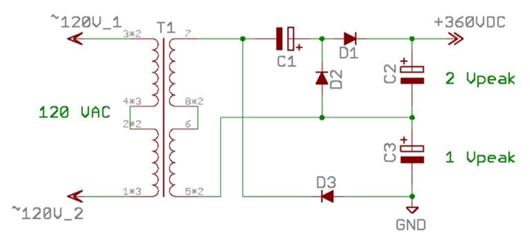
By taking the half wave voltage doubler and adding another half wave rectifier, we obtain a full wave voltage tripler depicted on the figure below. If we take the outputs between the two rectifiers then we obtain 3 Vpeak. Since C2 and C3 are each part of the total reservoir capacitance, and each is charged up on alternate half cycles, this now qualifies as a full wave rectifier circuit.
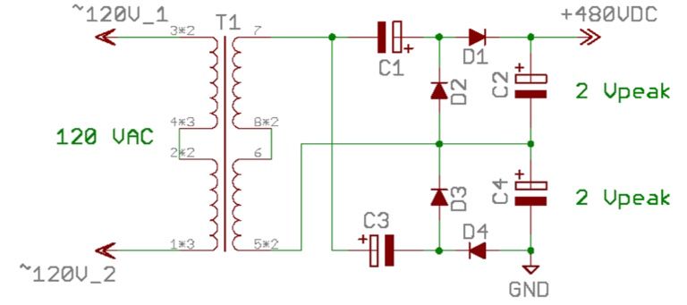
By connecting two half wave voltage doublers in parallel as shown on the figure below, we obtain a full wave voltage quadrupler.
When using a centre tapped transformer, it is possible to obtain several different voltage buses. The example of such topology is shown below.
